Article By :- Anirudh Sharma
EXPERIMENTAL INVESTIGATION OF MAGNETIC SUSPENSION SYSTEM
ABSTRACT
This project is based on suspension system of an automobile vehicle. This report gives information about electromagnetic suspension system. The aim of this project is to study and investigate the response of system, when it is subjected to road surface irregularities with the hope that it would help automobile industry. This project presents design, construction and working of one wheel vehicle electromagnetic suspension system. This system uses electromagnets as passive dampers, which is used to reduce displacement and acceleration of sprung mass in order to improve ride comfort. Main performance parameter of suspension system is vertical acceleration of chassis.
Problem definition
“Design and development of suspension system to minimize road shocks”
The aim of any suspension system is to provide a vehicle with a suspension that simultaneously resists dive, squat and roll, provides a comfortable ride with extensive axle articulation whilst maintaining equal pressure on all wheels as far as possible. In suspension system, there is always compromise between stability and comfort. So, suspension systems cannot offer all of the above requirements and have to compromise on ride quality which is associated with spring stiffness and damping coefficient. Springs that are too stiff springs provide a harsh ride and impede axle articulation. Soft springs provide a softer ride but cause unwanted effects on the handling of the vehicle, such as too much dive, squat and body roll. It is also not possible to use very soft spring in the suspension system as it reduces the ground clearance too much when loaded heavily. Another disadvantage of soft spring in suspension systems is the building up of high kinetic energy as the springs compress and the subsequent release of this energy when the springs return to their original state. This causes chassis twist and wheel bounce. Therefore, it is required to use dampers of high damping coefficient to gradually dissipate kinetic energy of spring. Again, these dampers oppose the spring to deflect effectively and hence deteriorate the comfort. So, it is required to develop a system that can improve comfort.
DESIGN OF EXPERIMENT
Project Concept
As discussed earlier, hydraulic dampers of conventional suspension system oppose the spring to deflect effectively and hence deteriorate the comfort. So, ride comfort of vehicle may be improved by introducing such type of dampers, which can help the spring to deflect properly and gradually dissipate the kinetic energy due to deflection of spring. In this project, electromagnet is used as damper to fulfill above objective.
Construction of suspension system
Purposed suspension system is modelled as shown in Figure. Since the model represents a suspension from one of the four corners of the vehicle, this system is referred as the “quarter-car” model. The lower mount is connected to the upper mount through the suspension spring. Sprung ma ss is placed on upper mount. Two electromagnets are mounted both on upper and lower mount.
Components used in suspension system are as follows:
Upper-mount:
The function of upper mount is to accommodate sprung mass and electromagnet. It is made up of wood. One end of spring is also connected to upper mount through spring plate. Dimension of upper mount: 38cm X 38cm X 3cm. There is one square hole at the center of upper mount having dimension: 10cm X 10cm X 1.2cm. The reason behind providing square hole is to constraint the horizontal movement of spring plate.
2) Lower-mount:
The jerk is applied to lower mount by lever, which is then transferred to suspension system. It is made up of wood. Two electromagnets are also mounted on upper side of it. Lower end of spring is connected to the lower mount through spring plate. . Dimension of lower mount: 38cm X 38cm X 4.8cm. There is one square hole at the center of lower mount having dimension: 10cm X 10cm X 3cm.
3) Spring plate:
The main function of spring plate is to connect spring with upper and lower mount. It is made up of Mild steel material. Both ends of spring are welded to spring plate. Both spring plates are connected to upper and lower mount through bolted joint. Dimension of spring plate: 10cm X 10cm X 1cm.
4) Spring:
Springs act as reservoirs of energy in suspension system. They store the energy due to the sudden force, when the vehicle encounters a bump or road
surface irregularities. This energy is released subsequently with the help of shock absorber. Dimensions of spring are as follows:
2) Connecting pin:
The main function of connecting pin is to support connecting block. It is circular rod in shape. Its diameter is 25mm and length is 20cm. It is supported in hole of base plate. Oiling is also carried out between connecting pin and connecting block to reduce friction.
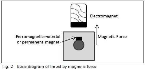
5) Electromagnet:
The role of electromagnet in this suspension system is as a damper. Core of electromagnet is made up of Mild steel in U shape. Coil of electromagnet is made up of copper having SWG 18. There are two electromagnets, which are mounted on both upper and lower mount through aluminum strips as shown in figure. Both coils are connected in parallel configuration with battery.
3) Connecting block:
It is the link between connecting pin and lever. It is solid block of dimension: 5cm X 5cm X 10cm. there are 2 through holes of diameter 25mm at right angle .
Experimental setup
It is the mechanism constructed to provide jerk to the suspension system. Purposed suspension system is constructed as shown in Figure. Jerk is applied at the one
end of lever, which is than supplied to lower mount of suspension system through circular plate. As we know that shock absorbed by suspension system is proportional to reduction in acceleration of upper mount with respect to lower mount, shock absorbed by the suspension system can be determined from the accelerator sensor.
pin
EXPERIMENTAL INVESTIGATION OF MAGNETIC SUSPENSION SYSTEM
ABSTRACT
This project is based on suspension system of an automobile vehicle. This report gives information about electromagnetic suspension system. The aim of this project is to study and investigate the response of system, when it is subjected to road surface irregularities with the hope that it would help automobile industry. This project presents design, construction and working of one wheel vehicle electromagnetic suspension system. This system uses electromagnets as passive dampers, which is used to reduce displacement and acceleration of sprung mass in order to improve ride comfort. Main performance parameter of suspension system is vertical acceleration of chassis.
Problem definition
“Design and development of suspension system to minimize road shocks”
The aim of any suspension system is to provide a vehicle with a suspension that simultaneously resists dive, squat and roll, provides a comfortable ride with extensive axle articulation whilst maintaining equal pressure on all wheels as far as possible. In suspension system, there is always compromise between stability and comfort. So, suspension systems cannot offer all of the above requirements and have to compromise on ride quality which is associated with spring stiffness and damping coefficient. Springs that are too stiff springs provide a harsh ride and impede axle articulation. Soft springs provide a softer ride but cause unwanted effects on the handling of the vehicle, such as too much dive, squat and body roll. It is also not possible to use very soft spring in the suspension system as it reduces the ground clearance too much when loaded heavily. Another disadvantage of soft spring in suspension systems is the building up of high kinetic energy as the springs compress and the subsequent release of this energy when the springs return to their original state. This causes chassis twist and wheel bounce. Therefore, it is required to use dampers of high damping coefficient to gradually dissipate kinetic energy of spring. Again, these dampers oppose the spring to deflect effectively and hence deteriorate the comfort. So, it is required to develop a system that can improve comfort.
DESIGN OF EXPERIMENT
Project Concept
As discussed earlier, hydraulic dampers of conventional suspension system oppose the spring to deflect effectively and hence deteriorate the comfort. So, ride comfort of vehicle may be improved by introducing such type of dampers, which can help the spring to deflect properly and gradually dissipate the kinetic energy due to deflection of spring. In this project, electromagnet is used as damper to fulfill above objective.
Construction of suspension system
Purposed suspension system is modelled as shown in Figure. Since the model represents a suspension from one of the four corners of the vehicle, this system is referred as the “quarter-car” model. The lower mount is connected to the upper mount through the suspension spring. Sprung ma ss is placed on upper mount. Two electromagnets are mounted both on upper and lower mount.
Components used in suspension system are as follows:
- Upper-mount
- Lower-mount
- Spring plate
- Spring
- Electromagnet
- Battery
Upper-mount:
The function of upper mount is to accommodate sprung mass and electromagnet. It is made up of wood. One end of spring is also connected to upper mount through spring plate. Dimension of upper mount: 38cm X 38cm X 3cm. There is one square hole at the center of upper mount having dimension: 10cm X 10cm X 1.2cm. The reason behind providing square hole is to constraint the horizontal movement of spring plate.
2) Lower-mount:
The jerk is applied to lower mount by lever, which is then transferred to suspension system. It is made up of wood. Two electromagnets are also mounted on upper side of it. Lower end of spring is connected to the lower mount through spring plate. . Dimension of lower mount: 38cm X 38cm X 4.8cm. There is one square hole at the center of lower mount having dimension: 10cm X 10cm X 3cm.
3) Spring plate:
The main function of spring plate is to connect spring with upper and lower mount. It is made up of Mild steel material. Both ends of spring are welded to spring plate. Both spring plates are connected to upper and lower mount through bolted joint. Dimension of spring plate: 10cm X 10cm X 1cm.
4) Spring:
Springs act as reservoirs of energy in suspension system. They store the energy due to the sudden force, when the vehicle encounters a bump or road
surface irregularities. This energy is released subsequently with the help of shock absorber. Dimensions of spring are as follows:
2) Connecting pin:
The main function of connecting pin is to support connecting block. It is circular rod in shape. Its diameter is 25mm and length is 20cm. It is supported in hole of base plate. Oiling is also carried out between connecting pin and connecting block to reduce friction.
5) Electromagnet:
The role of electromagnet in this suspension system is as a damper. Core of electromagnet is made up of Mild steel in U shape. Coil of electromagnet is made up of copper having SWG 18. There are two electromagnets, which are mounted on both upper and lower mount through aluminum strips as shown in figure. Both coils are connected in parallel configuration with battery.
3) Connecting block:
It is the link between connecting pin and lever. It is solid block of dimension: 5cm X 5cm X 10cm. there are 2 through holes of diameter 25mm at right angle .
Experimental setup
It is the mechanism constructed to provide jerk to the suspension system. Purposed suspension system is constructed as shown in Figure. Jerk is applied at the one
end of lever, which is than supplied to lower mount of suspension system through circular plate. As we know that shock absorbed by suspension system is proportional to reduction in acceleration of upper mount with respect to lower mount, shock absorbed by the suspension system can be determined from the accelerator sensor.
pin